.jpg) Flow Focusing technique:
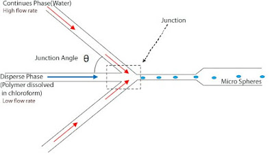
Flow Focusing technique:In our project the Flow Focusing technique is used to generate micrometer-scale sphere particles with mono disperse size distribution. In our project Flow Focusing technique utilizes the focusing of a disperse phase (a stream of polymer dissolved in chloroform) by a continues phase(water) liquid driven by a pressure drop. In this technique the continues phase fluid exerts pressure and viscous stress that force the dispersed phase fluid into a microthread. The breakup of the microthread then takes place inside of downstream of the orifice. The droplet breakup is a sensitive process and require skilful control of the fluid flow in the channels. Monodisperse droplets with a wide range of average diameter can be generated using this technique. Interestingly, the use of flow focusing technique which formed the microthread of the dispersed phase, is also allow generation of monodispersed droplets with diameter much smaller then the orifice size.
It is observed that the width of microthread at the channel junction decreased with increasing flow rates of the dispersed phase and the continues phase. When the microthread attained a characteristic width of several micrometers, droplet breakup occurred near the channel junction, which is independent of the flow rate of the dispersed phase.
Flow Focusing ray diagram:
 The disperse phase thread breaks at the orifice to release a micro sphere into the outlet channel. The size of these microspheres can be controlled primarily by flow rates of disperse phase & continues phase, Junction angle and the orifice size. The outer continuous water phase has a much higher flow rate than the inner disperse chloroform phase and these differential flow rates; force the polymer-containing liquid(polymer dissolved in chloroform) into a thin jet-like stream that breaks into droplets after passing the orifice. Each droplet then hardens into a particle called a microsphere. Controlling the flow of inner and outer phases will allow us to control the droplet size.
Effect of Junction Angle on the size of microspheres:
The effect of junction angle θ, in flow-focusing geometry on droplet formation is described here. Consider six microfluidic channel patterns with varied geometries. The schematic of the microfluidic channel pattern is shown in Figure. Each microfluidic Flow-Focusing device is comprised of three inlets with a common flow- focusing area. Inject the continues phase (stream of water) into two side inlet channels and a stream of polymer dissolved in chloroform as disperse phase into the middle inject channel. No surfactant should be added to either phase.
 The two continuous phase inlet channels originate from the same inlet hole in order to obtain the same and steady flow rates in both continuous phase inlet channels. The two flanking channels meet the central disperse phase inlet channel at the different junction angle in different microfluidic channel patterns. The microfluidic flow-focusing devices are made of PDMS (poly-di-methyl-siloxane), a transparent elastomer, using the soft lithography techniques. All channels in this experiment with different angles is made on the same silicon-wafer. Syringe pumps are employed for both injection of the disperse phase(polymer dissolved in chloroform) flow and the continuous phase(water) flow into microfluidic system. The flow rate of continuous phase was always kept higher than that of disperse phase.
In the experiment[Reference], the flow rate of disperse phase is fix at Qo, while varying the continues phase flow rate Qw. Five different continues flow rates Qw (50μl/h ≤ Qw ≤ 250μl/h) and two different disperse phase flow rates Qo (Qo =10μl/h, 20μl/h) are chosen. The complete process is observed under an inverted optical microscope. The sizes of droplets are measured by photographs taken by a CCD camera; coupled to the microscope. Researches usually uses image analysis software (Imaging Pro Plus 5.1, Media cybernetics, Inc.) to measure the sizes of the droplets and calculate the size distributions with coefficients of variation (CV) in diameter.
***************************************************************************************************************************************************************************************